

What Is the TCP/IP Model? The Four Layers That Run the Internet
Table of Contents
Why Layers
The internet connects billions of devices running different hardware, different operating systems, and different applications. Making all of that work together requires breaking the problem into layers, where each layer handles one part of the job and hands off to the next.
The TCP/IP model divides networking into four layers. Each layer has a specific responsibility, uses specific protocols, and communicates with the layers directly above and below it. A web browser does not need to know whether the network connection runs over WiFi, Ethernet, or cellular - it just talks to the transport layer. The transport layer does not care what application data it is carrying - it just delivers bytes reliably (or quickly, depending on the protocol).
This separation is what makes the internet work at scale. You can swap the physical network (Ethernet to WiFi) without changing your applications. You can run different applications (HTTP, DNS, SSH) over the same network without changing the infrastructure. Each layer is independently replaceable.

The TCP/IP stack in action: applications communicate through layered protocols. Each layer adds its own headers during transmission and strips them during reception. (Diagram: Wikimedia Commons, CC BY-SA 3.0)
Layer 1: Link (Network Access)
The link layer handles the physical transmission of data over a single network segment. This is where Ethernet, WiFi (802.11), and other physical network technologies operate.
At this layer, data is framed into link-layer units (Ethernet frames, WiFi frames) and addressed using MAC addresses. The link layer is responsible for getting a frame from one device to the next device on the same local network - one hop at a time.
When the BLEShark Nano captures WiFi frames, it is operating at this layer. Beacon frames, deauth frames, probe requests - these are all link-layer management frames that never leave the local wireless segment.
Layer 2: Internet
The internet layer handles routing data across multiple networks. The primary protocol here is IP (Internet Protocol), which provides logical addressing (IP addresses) and routing. When you send a packet to a server on the other side of the world, the internet layer determines the path through the network.
IP is connectionless and unreliable by design. It makes a best-effort attempt to deliver each packet, but provides no guarantees. Packets can arrive out of order, be duplicated, or be lost entirely. Reliability is left to the transport layer above.
IPv4 uses 32-bit addresses (4.3 billion possible addresses, long since exhausted). IPv6 uses 128-bit addresses (340 undecillion - effectively unlimited). Both versions handle the same fundamental job: getting a packet from source IP to destination IP across any number of intermediate routers.
Layer 3: Transport
The transport layer provides end-to-end communication between applications. The two primary transport protocols are TCP (reliable, ordered delivery) and UDP (fast, no guarantees).
TCP establishes a connection, tracks sequence numbers, retransmits lost segments, and ensures data arrives in order. This makes it suitable for web browsing, email, file transfers - anything where data integrity matters more than speed.
UDP skips all of that overhead. It sends datagrams with no connection setup, no sequence tracking, and no retransmission. This makes it faster and lighter, which is why it is used for DNS queries, voice calls, video streaming, and online games where speed matters more than guaranteed delivery.
Port numbers live at this layer. They identify which application on a host should receive the data. HTTP uses port 80, HTTPS uses port 443, DNS uses port 53. A single IP address can run dozens of services simultaneously because port numbers differentiate them.
Layer 4: Application
The application layer is where user-facing protocols operate: HTTP for web pages, SMTP for email, DNS for name resolution, SSH for remote shells, FTP for file transfers. These protocols define the format and semantics of the data being exchanged.
In the TCP/IP model, the application layer encompasses what the OSI model splits into three separate layers (session, presentation, and application). This is one of the practical simplifications that made TCP/IP win over OSI - fewer layers, less abstraction, easier to implement.
When a captive portal on the BLEShark Nano serves a login page, it is running an HTTP server at the application layer. The HTML page travels down through TCP at the transport layer, IP at the internet layer, and WiFi at the link layer before reaching the client's browser.
graph TD
    subgraph "TCP/IP Model"
        L4["Application Layer
HTTP, DNS, SMTP, SSH, FTP"]
        L3["Transport Layer
TCP, UDP"]
        L2["Internet Layer
IP, ICMP, IGMP"]
        L1["Link Layer
Ethernet, WiFi (802.11), ARP"]
    end
    L4 --> L3 --> L2 --> L1
    L1 -->|"Physical
transmission"| NET["Network"]
How Encapsulation Works
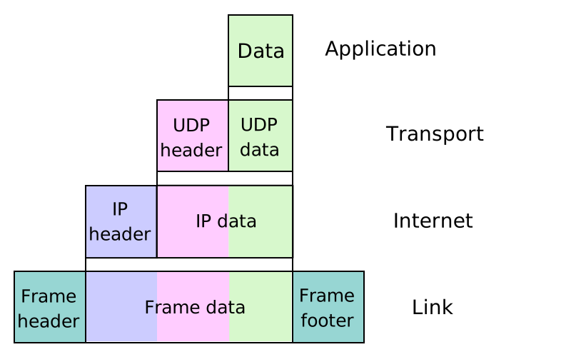
Data encapsulation: each layer wraps the data from above with its own header. The receiving side strips headers in reverse order. (Diagram: Wikimedia Commons, CC BY-SA 3.0)
When an application sends data, each layer adds its own header as the data passes down the stack:
- The application creates the data (an HTTP request, a DNS query, etc.)
- The transport layer wraps it in a TCP segment or UDP datagram, adding source port, destination port, and (for TCP) sequence numbers
- The internet layer wraps that in an IP packet, adding source IP and destination IP
- The link layer wraps that in an Ethernet or WiFi frame, adding source MAC and destination MAC
At each router along the path, the link-layer header is stripped and replaced (the MAC addresses change at each hop), but the IP header and everything above it stays the same. At the destination, each layer strips its header and passes the remaining data up to the next layer until the application receives the original data.
This is why packet capture tools show multiple layers of headers. When you inspect a frame in Wireshark, you see the Ethernet header, the IP header, the TCP/UDP header, and the application data - all nested inside each other like envelopes within envelopes.
graph LR
    subgraph "Encapsulation"
        DATA["Application
Data"] --> SEG["TCP/UDP Header
+ Data"]
        SEG --> PKT["IP Header
+ TCP/UDP + Data"]
        PKT --> FRM["Ethernet Header
+ IP + TCP/UDP + Data
+ FCS"]
    end
TCP/IP vs the OSI Model

The OSI model's seven layers, with data units at each layer. The TCP/IP model collapses these into four layers: Link (Data Link + Physical), Internet (Network), Transport, and Application (Session + Presentation + Application). (Diagram: Wikimedia Commons, CC BY-SA 4.0)
The OSI (Open Systems Interconnection) model has seven layers. TCP/IP has four. They describe the same networking reality, just at different levels of granularity:
| TCP/IP Layer | OSI Layers | Key Protocols |
|---|---|---|
| Application | Application, Presentation, Session | HTTP, DNS, SMTP, SSH, FTP |
| Transport | Transport | TCP, UDP |
| Internet | Network | IP, ICMP, IGMP |
| Link | Data Link, Physical | Ethernet, WiFi (802.11), ARP |
The OSI model is taught in courses and used in conversation ("that is a Layer 3 issue"). TCP/IP is what actually runs on the internet. In practice, most engineers use OSI layer numbers as shorthand even when discussing TCP/IP protocols - "Layer 7 firewall" means application-layer inspection, regardless of which model you subscribe to.
graph TD
    subgraph "Attacks by Layer"
        A4["Application"] --- A4A["SQL Injection
XSS
Command Injection"]
        A3["Transport"] --- A3A["SYN Flood
Port Scanning"]
        A2["Internet"] --- A2A["IP Spoofing
ICMP Flood"]
        A1["Link"] --- A1A["ARP Spoofing
Deauth Attack
MAC Flooding"]
    end
Why This Matters for Security
Security attacks target specific layers. ARP spoofing is a link-layer attack. IP spoofing targets the internet layer. SYN floods hit the transport layer. SQL injection targets the application layer. Understanding which layer you are operating at determines which tools, defenses, and detection methods apply.
The BLEShark Nano primarily operates at the link layer - capturing and analyzing WiFi and BLE frames. When it detects a deauth attack, it is seeing a link-layer management frame. When it captures a WPA2 handshake, it is collecting the EAPOL frames that carry transport-layer key negotiation. Knowing where each attack sits in the stack is what lets you choose the right tool for detection and testing.